Design of a vertical layout scheme.
The design of a vertical layout scheme for an urban area is carried out to fundamentally link the structural elements of the master plan with the terrain, with rivers, streams and other drains, with the road system, railway lines, bridges and other overpasses, with dams and other engineering structures.
Designing a vertical layout scheme is the first stage of a high-rise solution for a city territory when developing a feasibility study or a master plan for the city. The development of the scheme is carried out using the method of design (red) marks for individual planning elements - roads, paths, sites (Fig. 1).
The essence of this method is that on the general plan diagram, made on a geodetic basis with existing horizontal lines or marks, design marks are applied that characterize the planned relief and determine the organization of surface runoff of rain and melt water. This method makes it possible to determine the elevation, slope and altitude position of the designed relief. To determine these characteristics, black marks, red marks and work marks are used.
The black marks correspond to the marks of the existing terrain.
Red or design marks are marks of the transformed relief.
Working marks - the difference between the design red mark and the black mark of the existing terrain
Black marks are determined on the topographic plan at the corresponding characteristic points:
along the boundaries of the object (red lines),
at points of entry and entry into the territory,
at corner points and intersection points of axes at road intersections and path intersections,
at points of change in longitudinal relief (changes in slopes) along the axes or sides of driveways, roads, paths and alleys,
at the points of characteristic bends of the tracks on their axes or sides,
in the centers of platforms in the shape of a circle, oval, rectangle and other geometric shapes, or at the corner points of the platforms and at the junction points of the platform and the track;
All indicated black marks on the drawing of the relief organization diagram are numbered and applied below the outlined line, at each characteristic point.
Black marks at designated characteristic points are determined by interpolation.
Finding a mark on the surface. If the black score lies on the black horizontal line, then its value corresponds to the elevation of this horizontal line. The elevation of a point lying between the black horizontal lines is determined by the formula:
Нх=Нв+(На-Нв), where
Нв - assessment below the underlying horizontal line
On - estimate above the lying horizontal line
L - distance between horizontal lines (laying)
l-distance from the desired point to the underlying horizontal line.
The distances between points are taken according to the plan in accordance with the scale.
To solve this problem graphically, perpendiculars are reconstructed from points A and B in opposite directions, on which the excesses of points Ha and Hb relative to Hx are plotted on an arbitrary scale. The required point lies at the intersection of the line Na Hb with the segment that passes through the ends of the perpendiculars (Fig. 2).
The slope of the surface between two points is equal to the ratio of the difference in the elevations of these points to the horizontal distance between them:
i = (Na-Hv) / L.
The resulting value is usually rounded to thousandths.
The direction of the longitudinal slope of the street is shown using arrows along the streets and driveways from higher to lower elevations. The value of the longitudinal slope of the street is placed above the arrow, and the distance between the points limiting the section of the street with this slope is below it. Then they check the compliance of the actual longitudinal slope with the normative one on all elements of the street and road and path network. If the resulting longitudinal slope corresponds to the permissible values, it is rounded to thousandths (in ppm) and accepted as the design one. If the existing slope does not meet regulatory requirements, then when determining the design (red) marks, it is corrected and a design slope is assigned, which is plotted on the drawing above the extension arrow (Fig. 3).
Red marks are applied on the drawing of the relief organization diagram, at the corresponding characteristic points, on top of the extension line above the black mark. In this case, red marks should be assigned in such a way that the working marks, if possible, do not exceed ± 0.5 m.
For the city's road network, the nature of the transverse profiles and the maximum longitudinal slope are designed in accordance with the design parameters of streets and roads. Design longitudinal and transverse slopes for elements of the road and path network of parks are established in accordance with permissible slopes depending on the type of planning element.
For asphalt and cement pavements, the minimum transverse slopes are 15-25 °/oo. In flat areas (less than 4 °/oo), when laying streets and roads, their roadways are designed along a tray by constructing a saw-tooth longitudinal profile, with rainwater wells of the drainage network placed in low places (Fig. 4).
In Fig. Figure 5 shows the stages of making the final decision when developing a vertical layout scheme.
The working estimate indicates the amount of cutting or adding soil at a given point. It is applied to the left of the leader line on the drawing of the relief organization diagram, at the corresponding characteristic points.
Thus, having determined the red (design) marks at all characteristic points, assigning the permissible slopes of all elements of the street-road and road-path network, in accordance with regulatory requirements, the design high-rise frame of the facility territory is formed.
Calculation of black, red and working site marks
| Change |
| Sheet |
| Document no. |
| Signature |
| date |
| Sheet |
| 4 |
| TSTU.08.03.01.21-2016 PZ |
The site is leveled to eliminate the unevenness of the natural terrain and give it the slopes specified by the project.
The excavation work for the vertical leveling of the site includes: 1) removal of the plant layer of soil;
2) development of excavations;
3) formation of embankments;
4) moving soil from the excavation to the embankment of the site;
5) transportation of excess soil off site;
6) leveling of soil delivered by transport vehicles;
7) soil compaction;
 site surface planning;
9) planning of site slopes;
10) development of soil for the foundation of the structure.
We carry out the vertical planning of the site to a given elevation, determined from the condition of zero balance of soil masses, in which the volume of soil in excavations and embankments is equal to each other.
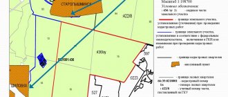
The assignment for developing an earthworks project specifies a construction site plan measuring 200˟150 m with contour lines; we calculate the volume of planning work using the square method. To do this, we divide the given area with a grid of squares with a side of 50 m, and the condition of passing through the square is no more than two horizontal lines (Fig. 1).
| Change |
| Sheet |
| Document no. |
| Signature |
| date |
| Sheet |
| 5 |
| TSTU.08.03.01.21-2016 PZ |
Rice. 1. Site diagram
Determine the black marks of the vertices of the squares. Black marks are marks of the natural terrain of the vertices of the squares, which are found by interpolation accurate to the second digit. To do this, draw a straight line between complex horizontal lines through the top of the square at the shortest distance (perpendicular). According to the accepted scale of the construction site, on the perpendicular we find the distance between the horizontal and the top of the square. Knowing the excess between the horizontal lines, we find the black mark using the formula:
where is the elevation of the lesser horizontal line, m; — horizontal pitch, m; – distance from the adjacent horizontal line with the lowest elevation to the top of the square, m; – minimum distance between horizontal lines along the perpendicular, m.
The average level (subject to a zero balance of earth masses and the use of the square prism method) is determined by the formula:
| Change |
| Sheet |
| Document no. |
| Signature |
| date |
| Sheet |
| 6 |
| TSTU.08.03.01.021-2016 PZ |
Where ;
; – the sum of the black marks of the squares in which one, two and four corners meet, respectively; – the number of squares on the construction site. Red (design) marks of the tops of the squares are determined taking into account the slope of the construction site according to the formula:
where is the average surface elevation, m; – specified slope of the site; – the distance from the tops of the squares to the conditional axis of symmetry of the construction site.
The slope of the construction site is formed by rotating the horizontal plane of the site at a mark around an axis located in the center of the site by the amount of a given slope in the direction of decreasing the black marks.
When finding the red marks, it is necessary to pay attention to the increase or decrease of the design marks relative to the horizontal plane with the mark.
Working marks at the vertices of the squares are determined by the formula:
where is the red mark, m; – black mark, m.
We record black, red and working marks at the top of the square according to the following scheme: the plus sign means an embankment, the minus sign means a recess.
| Change |
| Sheet |
| Document no. |
| Signature |
| date |
| Sheet |
| 7 |
| TSTU.08.03.01.021-2016 PZ |
We place the line of zero work in figures with marks of different signs and draw them on the drawing of the site plan with straight lines within each figure of the planning grid at points with zero values of work marks.
The location of the points is determined graphically. The graphical method of finding zero points consists in large-scale plotting of segments, which are working marks with opposite signs, in connecting their ends with a straight segment; the intersection of this segment with the side of the square forms the zero point. Connecting the zero points to each other with straight line segments gives a line of zero works 0-0.
A diagram of the site with marked marks and a line of zero works is shown on sheet 1 of the graphic part of the project.
The calculation of black, red and working marks is summarized in Table 1. Table 1 - Sheet for calculating site marks
| Top of the square | Black mark | Red mark | Working mark |
| Formula | Meaning | Formula | Meaning |
| A1 | 47,64 | 47,3 | -0,34 |
| A2 | 47,85 | 47,3 | -0,55 |
| A3 | 47,82 | 47,3 | -0,52 |
| A4 | 47,64 | 47,3 | -0,34 |
| A5 | 47,26 | 47,3 | 0,04 |
| B1 | 47,63 | 47,6 | -0,03 |
| B2 | 47,64 | 47,6 | -0,04 |
| B3 | 48,00 | 47,6 | -0,4 |
| B4 | 47,74 | 47,6 | -0,14 |
| B5 | 47,38 | 47,6 | 0,22 |
| IN 1 | 47,60 | 47,9 | 0,3 |
| AT 2 | 47,84 | 47,9 | 0,06 |
| AT 3 | 48,00 | 47,9 | -0,1 |
| AT 4 | 47,89 | 47,9 | 0,01 |
| AT 5 | 47,54 | 47,9 | 0,36 |
| G1 | 47,28 | 48,2 | 0,92 |
| G2 | 47,64 | 48,2 | 0,56 |
| G3 | 47,75 | 48,2 | 0,45 |
| G4 | 47,73 | 48,2 | 0,47 |
| G5 | 47,35 | 48,2 | 0,85 |