Definition of the concepts of PPT and PMT
PMT - a territory surveying project - is a special documentation classified as urban planning, which is created taking into account certain types of activities that require land surveying within the site, in other words, if a common site must be divided into smaller ones, there is a need to formalize this project.
NOTE. It is not defined in cadastral records and differs from land surveying for the purpose of allocation. Information from the PMT is publicly available on the websites of municipal architectural departments (geodetic department).
PPT - a territory planning project - is also an urban planning document and is closely related to the land surveying project, but its content reflects in more detail the characteristics of the objects existing on the territory and their parameters, as well as the location zones of the planned construction projects.
Purpose
The legislative description and content of documents are given in the Town Planning Code of the Russian Federation:
- Article 42 – planning project;
- Article 43 – land surveying project.
From a technical point of view, such documents represent the details of the Master Plan for the development of a city or other populated areas, although formally (from a legal point of view) they are not related to each other. A comparison of these types of documentation is presented in the table.
| compared characteristic | Territory planning project | General plan |
| what objects are being described | only a separate element of a settlement (it belongs to the so-called planning structure) - these can be separate areas, blocks, etc. | the settlement as a whole (a plan for the development of the territory of a particular city is presented) |
| what drawings are included in the document | detailed drawing that fully reflects the layout of the area |
|
| what is included in the descriptive (text) part of the document |
|
|
Thus, the documents reviewed relate to project documentation, and their main goal is to reflect the existing boundaries of the entire settlement and its individual zones (external and internal). In this case, the boundaries of all land plots are taken into account - those already developed, as well as those with planned development (in this case, the expected terms and stages of development of the territory are additionally indicated).
For example, on a city map, as a rule, several such planning zones are outlined. Each of these zones has its own names, which are usually given by the names of the regions and river banks (for example, the Right Bank of the Irtysh).
For each project, one Administration Resolution is drawn up signed by the head of the locality (in the case of a regional center - the mayor), as shown in the figure below. The document contains:
- the content of the changes made (with further development of the territory, the formation of new areas by dividing or merging existing ones);
- the area of each zone - residential buildings, road zones, streets, green areas;
- instructions to various Departments of the local Administration describing further actions in connection with the changes made.
The appendices to this Resolution contain a detailed description of the main indicators of the territory (technical and economic):
- the area of each zone (residential, streets, roads, etc.);
- detailed data for each zone (area of residential buildings of different heights - 1-2 floors, 3-5 floors, 6-18, from 18);
- building density;
- population size and density;
- data on objects related to the educational sphere (locations, visits per shift, minimum areas);
- data on healthcare facilities;
- data on the facilities of physical culture and health centers with their areas given.
For each of these parameters, 2 values are indicated - currently existing and planned.
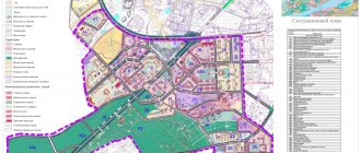
The second part of the application is the actual layout of the territory, reflected in a diagram with symbols.
Why are PPT and PMT needed?
These projects are used for:
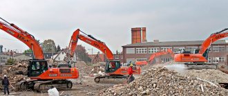
- Preparation for construction work;
IMPORTANT. These documents can be used not only on empty land, but also on areas with established infrastructure.
- Planning construction in conditions of already erected capital buildings;
- Determining the boundaries of use of shares of a land plot in common shared ownership;
- Alienation of the encumbered part of the site, delimited from the general territory;
- Resolving disputes about land boundaries.
These two documents are so mutually dependent that when creating one of them, the need to create the other follows.
Application of PMT and PPT
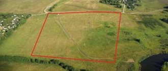
Since these documents are based on the land surveying procedure, they are used for lands that are in shared ownership, for example:
- for agricultural lands, since the total territory, put on one cadastral register under one number, allows division on the basis of PMT and PPT;
- to obtain permission to construct a linear facility;
- to register ownership of a share of a plot in the local area of an apartment building;
- for lands intended for individual housing construction.
Linear object
The planning project for an object of linear significance consists of the main part that needs to be approved and materials to justify it. The main part includes provisions where data regarding the placement of linear objects is indicated. The substantive materials are presented in an explanatory note and a graphic part.
It reflects:
- route plan, which indicates the designation of transport networks, communication lines, power lines;
- boundaries of the territories within the boundaries of which the construction of a linear facility is planned.
Design and survey of the territory of a linear facility
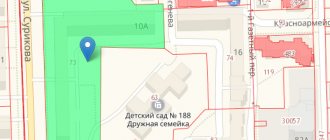
The figure shows a project for the design and survey of the territory on which the linear facility will be built.
Composition of the land surveying project
The PMT begins with a title page with information about the contractor and information about its structure and content. It consists of a text part and drawings, as well as materials for justifying this project.
Text part
- Information about the area of land formed, as well as possible methods of their formation;
- Information on the area of land related to public property, including for reservation and (or) withdrawal for municipal or state needs;
- Type of permit for the use of the created land plots in accordance with the territory planning project.
Blueprints
- Boundaries of existing objects or only planned ones (if the land surveying project is carried out as part of the PPT);
- Red lines approved in the PPT. Intended to indicate existing or planned construction projects;
- Indentation lines from the red lines to determine the locations of permissible placement of buildings, structures, structures;
- Areas of influence of public easements.
Justification materials contain boundaries
- Zones with special conditions of use;
- Protected natural lands;
- Objects of cultural heritage;
- Existing land plots;
- Capital construction projects.
Composition of the planning project
Any project that describes one or another element of the planning structure of a city or other populated area consists of technical (drawings) and descriptive (analytical materials) parts. Requirements for maintenance are strictly regulated by law, therefore, regardless of the purpose, location and other features of the territory, one should proceed from the following sections of the planning project:
- The main part is the actual drawing (scheme) of the site. On it are applied:
- all boundaries of built-up, developed areas, as well as zones where construction of residential and/or industrial facilities is proposed;
- the so-called red lines, which highlight the boundaries of the land with linear objects.
- The analytical part is a detailed provision containing materials on the proposed development of the territory, as well as on the technical characteristics of development and their changes over time:
- residential buildings;
- industrial premises;
- objects of any infrastructure serving the area (roads, utilities, hospitals, schools, etc.);
- the order of introduction of objects that are supposed to be built on this territory.
- Finally, there is a separate section with materials substantiating the features of just such a project:
- results and interpretation of engineering research results;
- justification of the boundary of each zone, as well as possible changes to this boundary provided for in the development plan;
- diagram with the location of each capital object;
- passages to all bodies of water (artificial and natural) intended for free access;
- a complete list of planned activities related to nature protection, civil defense measures, environmental protection of the territory (especially for those settlements that are located near nuclear power plants);
- the so-called vertical layout of the site, as well as other materials that take into account the individual characteristics of the land plot.
An example of a real project is shown in the figure.
Preparation requirements
The requirements themselves are enshrined in law, in articles of the Town Planning Code of the Russian Federation. In general, we can highlight the following important points in the design of a territory surveying project:
- Preparation on paper of at least two copies; at the request of the customer, also in electronic format;
- It is stitched and sealed with the signature and seal of the cadastral engineer, which is placed on the title page, on the plan itself and on the back of the last sheet of the project;
- Computer graphics tools are used, or in a combined way. All corrections must be certified by the signature and seal of a specialist;
- A4 sheets; Larger paper can only be used for design purposes;
- All sheets are numbered, except for the appendix;
- Empty fields are not removed; a dash is placed in them;
- Compiled based on information from a cadastral extract or territory plan;
- Cartographic materials or land survey documentation may be used;
- Use only Russian language and Arabic numerals;
- Special rules for transferring information from one section to the next sheet;
Requirements
The project being drawn up regarding the location of existing and only planned linear objects must be drawn up taking into account the following requirements and standards :
- The formation of a plan is carried out exclusively after drawing up a task for its execution;
- The creation of the plan can be carried out by a specialist who has the appropriate qualifications as a cadastral engineer and is authorized to formulate the route of a linear object. Such a specialist may be a registered individual. a person, as well as an employee of a private company or municipal body;
- Drawing up a plan for the passage of a linear object must have a basis in the form of legal acts of various authorities;
- In the process of carrying out work, the available information regarding land plots, the objects located on them, as well as passing linear structures must be taken into account;
- The developed plan must be subject to approval at an open hearing in the presence of all persons whose rights or interests may be affected in the process of laying communications and other facilities;
- The drawn up project must be approved by the municipality body, as well as by those services that monitor compliance with certain standards (engineering, construction, environmental), etc.
Step-by-step instructions for preparing PMT and PPT:
There are two options for preparing these projects: contacting the administration or a commercial campaign. In general, the algorithm of stages will be the same for PPT and PMT, since these documents are closely interrelated.
Contacting the administration is possible if the local municipality can offer such services.
- An application is submitted to an authorized person.
- Attached are the following documents:
- certificate of ownership;
- a sketch of the general plan of the land (plus a communications diagram);
- cadastral extract for the plot;
- extract on the presence/absence of permanent buildings;
- topographic plan (with communications).
- Based on them, the preparation of the project begins, where attention is paid to:
- soil structure;
- architecture;
- environmental friendliness of work;
- technical support;
- development results.
- If the decision is positive, then a technical specification is drawn up and cadastral manipulations are carried out.
- PPT and PMT are being developed.
- The PMT is agreed upon with the electric grid and water utilities at public hearings.
Everything is done for free. Completion period: within two months.
Contacting a special company is necessary when the administration has refused an application for projects. Then an agreement is concluded with an architectural company. In this case, the list of documents is identical, only the sketch can be excluded from the General Development Plan. All other actions are similar to administrative ones.
The period can be one month, the cost depends on the scope of work and the contract.
Samples for reference
Here is one of the project sheets:
Here you can see the title page of the territory surveying project:
This is what the territory planning project looks like:
This is what the survey project drawing looks like:
These projects are not easy to obtain, but they are necessary. This makes it possible to realize the prospects of the owner of the site for further free use of the land and for large developments.
Gas pipeline
Drawing up a gas pipeline planning and surveying project is no less labor-intensive process. The gas pipeline PP&MT includes the following general provisions:
- Information about populated areas included in the gas pipeline outlet system.
- Information about mineral deposits in the territory of the gas pipeline.
- Information on the presence of specially protected natural areas in the territory of the gas pipeline.
- Drawings of each individual section and settlements adjacent to the gas pipeline branch.