Types of engineering systems of a residential building
Support for comfortable conditions and normal functioning of a residential building is provided by a whole range of engineering systems. The main ones include the following communications:
- cold and hot water supply;
- water disposal and sewerage;
- heat supply;
- gas supply;
- electrical wiring and low-current networks;
- ventilation;
- garbage chutes;
- elevator facilities, etc.
Not only the convenience, but also the safety of residents depends on the technical condition of these networks. This places increased demands on the timeliness and quality of restoration work. This especially applies to the repair of in-house gas supply systems, electrical wiring and other utility networks.
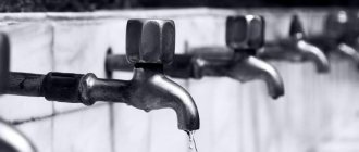
Definition and purpose of the internal water supply system
Internal water supply is pipes and devices that ensure the delivery of hot or cold water from the external water supply to consumers inside the building. Purpose – transportation of liquid of standard parameters: temperature, quality, pressure.
It is not allowed to connect a drinking water supply line to a water supply network supplying process water that is not suitable for drinking.
The internal water supply provides water for household plumbing, technological, and fire-fighting equipment. It is supplied from the central water supply of the settlement, or from a separate well or natural source. The type of internal water supply is influenced by technical capabilities, sanitary and hygienic and fire safety requirements, as well as the economic feasibility of the project.
Current and major repairs
Work to restore the engineering systems of an apartment building is divided into current and major repairs.
Current repairs of in-house engineering cold water supply systems and other communications include the elimination of local faults and malfunctions. During such repairs, individual elements of the system that are damaged, defective, or have served their intended service life may be replaced. For example, sections of pipelines, shut-off valves, power distribution devices, etc. are being replaced. Regular maintenance allows you to extend the service life of utilities and ensure their proper operation with maximum efficiency.
A major overhaul of in-house engineering systems involves their complete replacement or the replacement of a significant part of them. It is envisaged to be carried out when certain periods are reached, at which the wear of the equipment approaches a critical level.
Scope of work for major repairs
The list of works during major repairs is individual for each type of utility network. It also depends on their technical condition and configuration features.
When repairing in-house heating and water supply engineering systems, risers and distribution lines, shut-off, shut-off and control, and safety valves are replaced. Pumping and control equipment may change. Heating networks additionally provide for system balancing, replacement or repair of air vents, installation of an individual heating point and other equipment. Heating radiators or other heating devices in common areas are being replaced.
Major repairs of water drainage and sewerage include the replacement of sewer risers and deck chairs. The internal drainage of the house is also changed or reconstructed, and a drainage system is installed. Sewage valves are being installed, which ensure more comfortable use of the system and prevent emergency situations.
The overhaul of in-house power supply systems includes the replacement of electrical wiring and input and distribution devices. New house, entrance, and floor electrical distribution panels are being installed, and protective equipment is being changed. This also includes the replacement of general building lighting networks, emergency lighting, and outdoor lighting. Photoswitches and other advanced equipment can be installed to increase the efficiency and economy of the system. The power supply networks for the engineering equipment of the house are changing.
Gas supply networks are replacing in-house and façade gas pipelines. New gas equipment and shut-off valves are being installed. Gas distribution lines are being replaced or repaired.
Major ventilation repairs in an apartment building include cleaning ventilation ducts and replacing ventilation grilles. When mechanically driven forced ventilation is used in a building, work is carried out to diagnose and overhaul the equipment.
In-house water supply and sewerage devices. Water supply networks consist of a main line, service and fire risers, a distribution line, water supply and shut-off valves (taps, tanks, valves, etc.).
The network layout can be horizontal or vertical.
Horizontal wiring is used in low-rise buildings (up to two floors high) when sanitary fixtures are scattered across floors. In multi-storey sectional buildings, in which devices are located vertically, one above the other, it is possible to carry out horizontal and vertical network wiring.
In large-panel residential buildings, internal water supply systems are made, as a rule, with bottom wiring. The main pipelines are laid in the technical undergrounds of buildings or semi-through channels. The intra-house water supply network is connected to the street main by a special input.
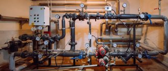
In case of insufficient guaranteed pressure, cold water supply pumps are installed at the water supply inlet. Typically, three pumps are installed: two of them provide water supply with minimum and maximum water withdrawal, the third is a backup.
To automatically control the pumps, two electric contact pressure gauges are installed on the pressure pipeline.
Pressure regulation in the pressure pipeline of the cold water supply system is carried out to protect the cold and hot water supply pipelines from possible damage when the pressure increases, as well as to smooth out hydraulic shocks when the pumps are turned on. Constant pressure regulation is carried out by a direct-acting pressure regulator 25ch10Нж, £>у=150 mm “after itself”. The regulator is installed vertically with the membrane drive upward, on a straight horizontal section of the pipeline.
The pressure of the regulated medium is formed by connecting the impulse tube to the sensitive element of the regulator - the membrane head. The connection point for the impulse tube is located at a distance of 1.5 m from the regulator in the direction of flow. A valve is installed on the impulse line and a pressure gauge is installed near the pressure tapping point. The temperature of the controlled environment should not exceed 40 °C. The maximum pressure on the regulator membrane device should not exceed the upper limit of the regulated pressure setting. The regulator dead zone is ±10-12% of the set pressure value.
Hot water supply. Water is heated in the coils of kitchen fires, in hot water columns, or supplied to sinks, sinks, showers and bathtubs from boiler rooms, boiler rooms and heating plants.
House sewerage consists of pipelines that drain wastewater from receiving devices (sinks, toilets, bathtubs), followed by the direction of wastewater from sewer risers into yard networks.
Internal sewer pipelines consist of risers and inclined branches from receiving devices to risers. To ventilate the home sewer network, risers are used as hoods, for which they are installed above the roof to a height of 0.7 m or more. To clean sewer pipelines, inspections are installed in appropriate places (at bends and risers).
Internal sewerage systems have outlets into the inspection wells of the yard network from each section of the house separately or common outlets at the ends of the building from a combined collection pipeline laid in the basement.
Sanitary units (bathroom and restroom) in a number of series of large-panel and large-block buildings are made in the form of a spatial box-shaped block - a sanitary cabin.
The equipment of sanitary cabins includes:
- pipelines for cold and hot water, sewerage and gas supply (with decentralized preparation of hot water from geysers);
- sanitary fixtures: bath, washbasin, toilet and heated towel rail (heater);
- fittings;
- toilet set;
- ventilation devices;
- heating devices.
Local (stove) heating is used in low-rise buildings up to two floors high. Central heating systems are installed in large residential and cultural buildings. Currently, stove heating is still widespread. Heating stoves are mainly used intermittently (with one or two fireboxes during the day). The use of low-capacity furnaces (with low mass) is possible under the condition of a long or continuous race.
The main elements of heating stoves are the firebox, the storage part (with a channel system), and the chimney.
The stoves are laid out of red, well-burnt and refractory bricks (the firebox should preferably be made of refractory bricks), as well as ceramic and linear blocks.
Night heating devices include kitchen fires, mainly intended for cooking, but also serving to heat the room. In this case, heating panels made of brick walls are installed on kitchen fireplaces.
To remove flue gases from stoves and hearths, chimneys are installed, which can be mounted (when installed directly on the stove), root (in the form of an independent riser with channels) or wall-mounted (the smoke channel is located in a solid stone wall).
When installing stoves, hearths and smoke ducts near wooden walls and partitions, it is necessary to provide a deviation from them of at least 38 cm. If there is a fireproof or fire-resistant heat-insulating layer, the deviation from the partitions and walls is allowed less (25 cm).
At the ends of the wooden partitions adjacent to the stoves and smoke ducts, vertical cuts are made between them.
For long-term operation of heating stoves and kitchen hearths, the correct design of fire doors is of great importance. The fire doors are sealed into the masonry using strip steel tabs attached to the door frame. The combustion hole is covered with a brick “in the lock” or with a lintel.
Stationary floor-standing electric stoves consist of a housing, an oven, burners, a control panel and control equipment (power switch and thermostats).
The body of the stove is made of sheet steel and coated with enamel on the outside. Cast iron burners consist of a cast iron body, in the grooves of which two or three nichrome heating coils are pressed; The insulating material is periclase.
One- and two-pipe systems with double adjustment valves are also used.
On each riser, at the point where it connects to the distribution pipelines, taps are installed to regulate water flow and turn off the riser in case of repairs. To drain water, the risers have fittings plugged with plugs.
Subject to the receipt of coolant from thermal power plants and large (district) central heating boiler systems, individual residential buildings are connected to the main pipelines through individual or central heating points (ITP and central heating points).
Connection to such heating networks can be:
- dependent, with an elevator, if the pressure in front of the elevator is not less than 0.15 MPa (1.5 kg/cm2) and the pressure in the return pipeline of the heating network is not more than 0.5 MPa (5 kg/cm2);
- dependent, with a pump on the jumper, if the pressure difference is insufficient for the operation of the elevator;
- dependent, with a pump on the supply pipeline after the mixing jumper, if it is necessary to increase the pressure difference;
- dependent, with a pump on the return pipeline, when the pressure in the return pipeline is higher than permissible for the heating system;
- direct, when the calculated water temperature in the supply pipeline and pressure are acceptable for this system;
- independent through a water heater with an expansion tank and air collectors, when the pressure in the heating network is higher than permissible for a given system, and vice versa, when the pressure in the system of a given building is higher than permissible for the heating network or other systems connected to it (for example, high-rise buildings).
Connection of hot water supply systems to heating networks is carried out according to the following schemes: two-stage sequential or mixed connection of water heaters (if the maximum heat consumption for hot water supply exceeds the maximum heat consumption for heating).
Centralized hot water supply systems from thermal power plants or district boiler houses are carried out with lower wiring. Both mains and hot water risers have circulation pipelines, and the risers are connected by circulation lines to a return pipeline. The hot water temperature must be maintained between 65-70 ° C to ensure the safety of threaded connections. It is advisable to make hot water supply pipelines from galvanized pipes, which ensures reliable operation and reduces the frequency of repairs of hot water supply systems.
Cast iron radiators, stamped steel panels, partition heating panels and baseboard-type convectors are used as heating devices. The surface area of heating devices is determined by the heat losses of the room at the calculated outdoor air temperatures for a given area, as well as by the temperature difference of the water in the device, which depends on the riser design and the method of its calculation. Therefore, in rooms of the same heat loss and location in the house, heating devices with different surface areas can be installed.
Air is released from systems with lower wiring using special air valves installed in devices on the upper floors. In systems with overhead distribution, air is removed through air collectors installed in the attic.
Saving fuel and thermal energy is facilitated by the rational production of heat in local boiler houses by adjusting their work with the development of regime maps, providing fuel with the quality required for these boilers, and strictly observing the calculated temperature schedule and flow of network water.
The water temperature in heating systems, depending on the outside air temperature, is given in the “Rules and Standards for Technical Operation and Repair of Housing Stock.”
Gas supply devices. Gas equipment in residential buildings includes house gas heaters (from an ax device at the inlet and gas appliances (stoves, water heaters, heating stoves, etc.) using gas for heating. The house gas supply network consists of a main line, risers and a distribution network , made of black steel gas pipes. Riser pipes are laid in non-residential premises. The distribution network supplies gas to appliances (stoves, water heaters, stoves and boilers).
The rooms in which gas appliances are installed must be provided with good ventilation; the doors from these rooms must open outward. Gases must be vented from gas water heaters into separate exhaust ducts, and ventilation must be provided in rooms equipped with gas stoves.
Ventilation devices. Residential premises in most cases are equipped with a natural ventilation system (through vents and exhaust ducts), but in multi-storey buildings, ventilation shafts and exhaust chambers with thermal stimulants are sometimes installed in the attic.
For external ducts in buildings, internal steps and extension boxes are used, which are connected to the exhaust shaft in the attic.
Power supply devices. Electricity supply to residential buildings is carried out from transformer substations of the electricity supply organization. Electrical networks before the input device in houses are under the management and operation of the energy supply organization, and after the input device of a residential building - under the management and operation of the owner of the house.
Electrical networks are made three-phase four-wire with a tightly grounded neutral at a voltage of 380/220 V. Hidden electrical wiring is embedded in factories into large-sized building elements.
When laying open horizontally along the walls, the wires are laid parallel to the intersection lines of walls and ceilings at a distance of no less than 100 mm and no more than 200 mm from the ceiling or cornice.
Vertical laying of the wire (descents, ascents, branches) is performed perpendicular to the plane of the ceiling. Near doors and windows, the wire is laid at a distance of 100 mm from the edge of the door or window frame.
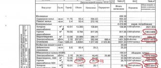
To account for the consumption of electricity spent on lighting staircases and the operation of elevators, boiler heating units, laundries, workshops, calculated electric meters are installed, which are mounted on panels or shields at a height of 1400-1700 mm from the floor in special metal cabinets with lockable doors, keys from which they are in DEZ (house management). Electricity meters are installed in apartments or on landings to account for the electricity consumed by residents. Electric meters are checked once every 5 years.
To save energy on lighting stairs and courtyards, it is advisable to use special photo switches F-2, which automatically turn on and off the lighting of stairs depending on natural light. Practice has shown that thanks to the use of photoswitches, the duration of lamp burning has decreased by approximately 2 hours per day.
Automatic photo switch F-2 is an electronic relay made of transistors and controlled by current from a photoresistor. The sensitive element of the photoswitch is a photoresistance, which changes the current conductivity depending on the degree of illumination.
To ensure stable operation of the device and ease of operation, it should be mounted in close proximity to the location where the lighting groups are distributed. To protect the device, install an additional fuse (no more than 6 A); If photo switches are made in a metal case, they are grounded.
Remote photoresistance is installed in places with natural light, the selection of which takes into account the presence of shading objects and neighboring structures, as well as artificial light sources. The length of the installation wire from the photoresistor to the device should not exceed 15 m.
The operating voltage of the F-2 photoswitch is 127-ШВ, dimensions 165ХИ0ХУ0 mm, weight 0.95 kg.
Garbage chute devices. In residential buildings with a height of four floors or more, household solid waste (MSW) is usually disposed of using garbage chutes. Waste from garbage chutes goes directly into collections (containers) located in the garbage collection chamber. Garbage chutes consist of a shaft, loading valves and garbage collection chambers with equipment.
The barrel and all its fixed connections (pipe joints, valve fastenings, etc.) must be moisture-resistant, smoke- and air-tight; the inner surface of the trunk must be smooth, without ledges, cavities, cracks or sagging; there must be a gate device in the lower part of the trunk (at the entrance to the waste collection chamber).
An open trunk of a garbage chute must be separated from building structures by soundproofing gaskets, have an effective ventilation system, and also include equipment for washing and cleaning the trunk. The ventilation duct of the barrel must have a smooth surface and be made of fireproof material.
Loading valves (buckets) must meet the following requirements: have dimensions that prevent the possibility of throwing into the barrel large objects exceeding the internal diameter of the barrel; be removable and easy to open, but at the same time provide a tight valve seal, eliminating smoke and air permeability; do not block the internal cross-sectional area of the trunk. In addition, its internal surface must be smooth and have an anti-corrosion coating. Loading valves are attached to the barrel through elastic gaskets.
Garbage collection chambers must have walls lined with ceramic tiles on the inside and a ceiling painted with oil paint. The dimensions of the waste collection chamber must ensure the normal placement and maintenance of containers, means of moving them, and the installation of the necessary sanitary equipment. Hot and cold water supply pipes with taps with a diameter of at least 15 mm and hoses for washing the chambers should be inserted into the chamber. The floor of the chambers is made waterproof with a slope of at least 1% towards the ladder or pit.
The pit in the waste chamber with a capacity of at least 30 liters is equipped with a removable grill. The chamber also contains a sink with a valve on the bypass pipe and a hand pump for pumping water from the pit to the sink. The drain in the floor of the garbage chamber is connected to a sewer pipe with a diameter of at least 100 mm.
The inside of the garbage chamber door must be lined with sheet steel and have a tight seal along the entire contour, as well as a locking device. Doors must open outward and be wide enough to accommodate a cart containing a container or garbage disposal.
Dust-proof and moisture-proof lamps are installed inside the chamber; The air temperature inside the garbage chambers must be at least 5 °C.
Garbage chambers are equipped with carts or other devices for moving containers and garbage collectors, and also provide access for garbage vehicles and arrange convenient passages for carts and containers from garbage chambers to parking areas for garbage trucks.
The garbage chamber must have natural exhaust ventilation through the garbage chute. If possible, the floor mark of the garbage disposal should be at sidewalk level.
Frequency of major repairs
The efficiency and security of networks depends on how timely their reconstruction is carried out. Each type of in-house engineering communications has its own frequency of major repairs. In particular, for the main networks, the regulatory documentation establishes the following deadlines:
- major repairs of in-house engineering heat supply systems - 25 years;
- hot and cold water supply - 15 years (with galvanized risers - 30 years);
- replacement of in-house power supply networks - 20 years;
- replacement of cast iron sewer risers - 40 years;
- replacement of plastic and ceramic sewer risers - 60 years.
If the deadlines for major repairs are violated, utility networks fall into disrepair. This results in emergencies that lead to significant material damage. There may also be a threat to the safety of residents and building maintenance personnel. Therefore, the organization operating a residential building is obliged to strictly control the service life of the systems and carry out repair work in a timely manner.
However, the need for major repairs may arise earlier than the deadline established by the regulations. The service life of systems depends on many factors, including the quality of installed elements, the quality of installation work, operating conditions, etc. Therefore, in some cases, critical wear may occur earlier. The presence of serious problems can be indicated by various disruptions in the operation of communications, for example, a significant decrease in water pressure on the upper floors, poor heating of heating radiators, the appearance of an unpleasant odor from the basement or from ventilation ducts, frequent blockages in sewer risers, malfunctions of electrical equipment, etc. d.
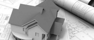
Internal network design
Providing the necessary pressure for drinking or domestic water to the consumer using pipes of minimal length is the main task of designing internal water supply.
Internal water supply fits into the interior of buildings or premises without disturbing the design and basic structure. Take into account the following:
- Calculations are based on the maximum volume of water consumed per unit of time (1 second).
- The flow rate in the internal water supply pipes, including fire protection, is no more than 3 m/sec.
- If there are two inputs, each of them is calculated at 100% load to ensure uninterrupted supply of one at a time when the second one is turned off. If there are more inputs, the liquid consumption is 50%.
- The internal water supply is laid from pipes, the diameter of which allows you to effectively use the pressure of the external water supply at the highest water consumption in the building.
- The diameter of the pipes of the ring jumpers corresponds to the largest diameter of the pipes of the water intake riser.
- Provision is made for the installation of vibration-isolating bases for pumping units.
- In apartment buildings or public buildings, the most hidden installation of internal water supply networks is carried out in rooms with a temperature of at least 2 degrees. Technical basements, attics, and underground utility channels are used.
In difficult cases, designing an internal water supply system, carrying out hydraulic calculations, and determining equipment parameters is carried out by specialists taking into account the requirements of SNiP 2.04.01-85*.
How to request early major repairs
Overhaul of engineering systems of residential buildings is carried out in accordance with the regional program, which sets specific deadlines for each building. Therefore, completion of work ahead of schedule is possible only if there are grounds.
To do this, residents of the building must submit a corresponding application to the HOA, management company or other organization on whose balance sheet the building is located. The application is drawn up in free form, indicating the essence of the problem, the date of the last inspection, and a description of the condition of the networks.
Based on the submitted application, examinations are carried out, during which the actual condition of engineering systems and the need for major repairs are assessed. After this, an application is submitted to make changes to the regional program, and emergency communications are overhauled.