What is a temperature chart and its purpose?
The temperature graph of a heating system is the dependence of the temperature of the coolant, which is water, on the temperature of the outside air.
The main indicators of the graph under consideration are two values:
- The temperature of the coolant, that is, the heated water that is supplied to the heating system to heat residential premises.
- Outdoor air temperature readings.
The lower the ambient temperature, the more it is necessary to heat the coolant that is supplied to the heating system. The schedule under consideration is constructed when designing heating systems for buildings. It determines indicators such as the size of the heating devices, the coolant flow rate in the system, as well as the diameter of the pipelines through which the coolant is transferred.
The temperature graph is indicated using two numbers, which are 90-70 degrees. What does this mean? These numbers characterize the temperature of the coolant that must be supplied to the consumer and returned back. To create comfortable indoor conditions in winter when the outside air temperature is -20 degrees, you need to supply coolant to the system with a value of 90 degrees Celsius, and return it with a value of 70 degrees.
The temperature graph allows you to determine whether the coolant flow rate is too high or low. If the temperature of the returned coolant is too high, this will indicate a high flow rate. If the value is underestimated, this indicates a consumption deficit.
The 95-70 degree schedule for the heating system was adopted in the last century for buildings up to 10 floors. If the number of floors in a building exceeds 10 floors, then the values taken were 105-70 degrees. Modern heat supply standards for each new building are different, and are often adopted at the discretion of the designer. Modern standards for insulated houses are 80-60 degrees, and for buildings without insulation 90-70.
Beginning of the 2021 heating season in Perm, the reliability of heat supply systems has been significantly increased
It should be noted that in preparation for the autumn-winter period in Perm, the reliability of heat supply systems has been significantly increased. Thus, power engineers of the Perm branch of T Plus PJSC carried out 25 major and medium repairs of main equipment and more than 60 current repairs of all types of main energy equipment and structures. In Perm, 28 km of the main “thermal arteries” were rebuilt on the central streets: Nikolai Ostrovsky, Newspaper “Zvezda”, Petropavlovskaya, Krisanova, Osinskaya, Krasnova, as well as on the right bank of the Kama - Marshal Rybalko and Sivashskaya streets.
Expert comments:
Maxim Ryabenko, technical director - chief engineer of Perm Grid Company LLC:
“Heating will appear in Perm residents’ apartments gradually, as pumping stations and heating mains are switched to winter modes. The commissioning period can take up to two weeks. The main responsibility for the timely release of heat into houses lies with service organizations - management companies and homeowners' associations. Their task is to monitor the operation of the energy installations of houses, so that air does not occur in the risers, and the coolant inside the building is distributed evenly. In the event of a lack of heating, citizens must contact their management companies and homeowners associations; contact numbers are indicated on receipts. You can also report the situation with the heat supply at home to the control room of Perm Network Company LLC by calling 281-72-99.”
Stanislav Baskakov, acting Director of PMUP "City Utilities and Heat Management":
“The summer months for a municipal enterprise invariably become the most important stage of work to ensure a successful heating season. Our organization prepared 14 boiler plants, 43 central heating stations and 243 km of heating networks for the heating season. In the meantime, although the heating season is just beginning, preparations for the next winter 2019-2020 will soon begin, namely the development of the next action plan. We will begin implementing this plan in January.”
Why do temperature fluctuations occur?
The reasons for temperature changes are determined by the following factors:
- When weather conditions change, heat loss automatically changes. When cold weather sets in, to ensure an optimal microclimate in apartment buildings it is necessary to expend more thermal energy than during warming. The level of heat loss consumed is calculated by the “delta” value, which is the difference between the street and indoors.
- The constancy of the heat flow from the batteries is ensured by a stable temperature of the coolant. As soon as the temperature decreases, apartment radiators will become increasingly warmer. This phenomenon is facilitated by an increase in the “delta” between the coolant and the air in the room.
The increase in coolant losses must be carried out in parallel with the decrease in air temperature outside the window. The colder it is outside, the higher the temperature of the water in the heating pipes should be. To facilitate the calculation processes, a corresponding table has been adopted.
Characteristics and release of coolant
SNiP 2.04.07-86 regulates the physical and chemical characteristics of the working fluid of heating systems, as well as the release parameters, its main provisions:
- In centralized heat supply systems for the needs of heating, ventilation, hot water supply and technical processes in industrial and public buildings, the main type of heat carrier is water.
- The release and regulation of heat supply is carried out centrally - at the heat source (CHP), in groups - in control units or central heating stations, individually - in ITP.
- For heating networks with a water working fluid, the supply of thermal energy according to the heating load or together with hot water supply is carried out according to the tables of the interdependence of the medium temperature on the environmental parameters.
- Regulation is carried out according to quantity (volume of water supplied) and quantitative-qualitative (volume-temperature) parameters.
- With centralized regulation in heat supply systems with a predominance of housing and communal loads of 65% or more, joint regulation for heating and domestic hot water is used. If the share of housing and communal services load is less than 65% of the total, and the share of hot water supply is less than 15% of the heating load, regulation is carried out according to the heating load.
- When adjusting the heat supply, in all cases, the limitation is the minimum temperature of the carrier in the main required to heat cold water in the DHW circuits connected to the heat supply line to the users: - for closed circuits (with an electric pump), the temperature in the heating system is taken to be at least +70 ° C; — for open-type gravity systems, the set water temperature in the heating pipes is at least +60 °C.
- When drawing up a temperature schedule for the heating system, take the average temperatures: - for the beginning and end of the heating season - +8 ° C; — in residential premises — +18 °C; — inside production workshops — +16 °С.
- For facilities in production and in public places, with a planned decrease in temperature after a shift and on weekends, volumetric and thermal regulation of the characteristics of the working fluid is implemented in heating points (TP).
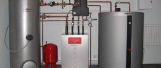
Rice. 3 Central heating units - appearance
What is a temperature graph
The temperature graph for coolant supply to heating systems is a table that lists the coolant temperature values depending on the outside air temperature.
A generalized graph of water temperature in the heating system is as follows:
The formula for calculating the temperature graph is as follows:
- To determine the coolant supply temperature: T1=tin+∆xQ(0.8)+(β-0.5xUP)xQ.
- To determine the return supply temperature, the formula is used: T2=tin+∆xQ(0.8)-0.5xUPxQ.
In the presented formulas:
Q – relative heating load.
∆ is the temperature pressure of the coolant supply.
β – temperature difference in forward and reverse supply.
UP is the difference in water temperature at the inlet and outlet of the heating device.
There are two types of graphs:
- For heating networks.
- For apartment buildings.
To understand the details, let’s consider the features of the functioning of centralized heating.
Blog about energy
Looking through the statistics of visits to our blog, I noticed that search phrases such as, for example, “what should be the coolant temperature at minus 5 outside?” appear very often. I decided to post the old schedule for the quality regulation of heat supply based on the average daily outside air temperature . I would like to warn those who, based on these figures, will try to figure out the relationship with housing departments or heating networks: heating schedules for each individual settlement are different (I wrote about this in the article regulating the temperature of the coolant). Heating networks in Ufa (Bashkiria) operate according to this schedule.
I would also like to draw your attention to the fact that regulation occurs based on the average daily outside air temperature, so if, for example, it is minus 15 degrees outside at night and minus 5 degrees , then the coolant temperature will be maintained in accordance with the schedule at minus 10 oC .
Typically, the following temperature schedules are used: 150/70 , 130/70 , 115/70 , 105/70 , 95/70 . The schedule is selected depending on specific local conditions. House heating systems operate according to schedules 105/70 and 95/70. Main heating networks operate according to schedules 150, 130 and 115/70.
Let's look at an example of how to use a chart. Let's say the temperature outside is minus 10 degrees. Heating networks operate according to a temperature schedule of 130/70 , which means that at -10 °C the temperature of the coolant in the supply pipeline of the heating network should be 85.6 degrees, in the supply pipeline of the heating system - 70.8 °C with a schedule of 105/70 or 65.3 °C with schedule 95/70. The water temperature after the heating system should be 51.7 °C.
As a rule, the temperature values in the supply pipeline of heating networks are rounded when assigned to a heat source. For example, according to the schedule it should be 85.6 °C, but at a thermal power plant or boiler house it is set to 87 degrees.
| Outdoor air temperature Тнв, оС | Temperature of network water in the supply pipeline T1, °C | Water temperature in the supply pipeline of the heating system T3, °C | Water temperature after heating system T2, оС | |||
| 150 | 130 | 115 | 105 | 95 | ||
| 8 | 53,2 | 50,2 | 46,4 | 43,4 | 41,2 | 35,8 |
| 7 | 55,7 | 52,3 | 48,2 | 45,0 | 42,7 | 36,8 |
| 6 | 58,1 | 54,4 | 50,0 | 46,6 | 44,1 | 37,7 |
| 5 | 60,5 | 56,5 | 51,8 | 48,2 | 45,5 | 38,7 |
| 4 | 62,9 | 58,5 | 53,5 | 49,8 | 46,9 | 39,6 |
| 3 | 65,3 | 60,5 | 55,3 | 51,4 | 48,3 | 40,6 |
| 2 | 67,7 | 62,6 | 57,0 | 52,9 | 49,7 | 41,5 |
| 1 | 70,0 | 64,5 | 58,8 | 54,5 | 51,0 | 42,4 |
| 0 | 72,4 | 66,5 | 60,5 | 56,0 | 52,4 | 43,3 |
| -1 | 74,7 | 68,5 | 62,2 | 57,5 | 53,7 | 44,2 |
| -2 | 77,0 | 70,4 | 63,8 | 59,0 | 55,0 | 45,0 |
| -3 | 79,3 | 72,4 | 65,5 | 60,5 | 56,3 | 45,9 |
| -4 | 81,6 | 74,3 | 67,2 | 62,0 | 57,6 | 46,7 |
| -5 | 83,9 | 76,2 | 68,8 | 63,5 | 58,9 | 47,6 |
| -6 | 86,2 | 78,1 | 70,4 | 65,0 | 60,2 | 48,4 |
| -7 | 88,5 | 80,0 | 72,1 | 66,4 | 61,5 | 49,2 |
| -8 | 90,8 | 81,9 | 73,7 | 67,9 | 62,8 | 50,1 |
| -9 | 93,0 | 83,8 | 75,3 | 69,3 | 64,0 | 50,9 |
| -10 | 95,3 | 85,6 | 76,9 | 70,8 | 65,3 | 51,7 |
| -11 | 97,6 | 87,5 | 78,5 | 72,2 | 66,6 | 52,5 |
| -12 | 99,8 | 89,3 | 80,1 | 73,6 | 67,8 | 53,3 |
| -13 | 102,0 | 91,2 | 81,7 | 75,0 | 69,0 | 54,0 |
| -14 | 104,3 | 93,0 | 83,3 | 76,4 | 70,3 | 54,8 |
| -15 | 106,5 | 94,8 | 84,8 | 77,9 | 71,5 | 55,6 |
| -16 | 108,7 | 96,6 | 86,4 | 79,3 | 72,7 | 56,3 |
| -17 | 110,9 | 98,4 | 87,9 | 80,7 | 73,9 | 57,1 |
| -18 | 113,1 | 100,2 | 89,5 | 82,0 | 75,1 | 57,9 |
| -19 | 115,3 | 102,0 | 91,0 | 83,4 | 76,3 | 58,6 |
| -20 | 117,5 | 103,8 | 92,6 | 84,8 | 77,5 | 59,4 |
| -21 | 119,7 | 105,6 | 94,1 | 86,2 | 78,7 | 60,1 |
| -22 | 121,9 | 107,4 | 95,6 | 87,6 | 79,9 | 60,8 |
| -23 | 124,1 | 109,2 | 97,1 | 88,9 | 81,1 | 61,6 |
| -24 | 126,3 | 110,9 | 98,6 | 90,3 | 82,3 | 62,3 |
| -25 | 128,5 | 112,7 | 100,2 | 91,6 | 83,5 | 63,0 |
| -26 | 130,6 | 114,4 | 101,7 | 93,0 | 84,6 | 63,7 |
| -27 | 132,8 | 116,2 | 103,2 | 94,3 | 85,8 | 64,4 |
| -28 | 135,0 | 117,9 | 104,7 | 95,7 | 87,0 | 65,1 |
| -29 | 137,1 | 119,7 | 106,1 | 97,0 | 88,1 | 65,8 |
| -30 | 139,3 | 121,4 | 107,6 | 98,4 | 89,3 | 66,5 |
| -31 | 141,4 | 123,1 | 109,1 | 99,7 | 90,4 | 67,2 |
| -32 | 143,6 | 124,9 | 110,6 | 101,0 | 94,6 | 67,9 |
| -33 | 145,7 | 126,6 | 112,1 | 102,4 | 92,7 | 68,6 |
| -34 | 147,9 | 128,3 | 113,5 | 103,7 | 93,9 | 69,3 |
| -35 | 150,0 | 130,0 | 115,0 | 105,0 | 95,0 | 70,0 |
Please do not rely on the diagram at the beginning of the post - it does not correspond to the data from the table.
Temperature graph calculation
The method for calculating the temperature graph is described in the reference book “Adjustment and operation of water heating networks” (Chapter 4, paragraph 4.4, p. 153).
This is a rather labor-intensive and time-consuming process, since for each outdoor temperature several values need to be counted: T1, T3, T2, etc.
To our joy, we have a computer and a spreadsheet processor MS Excel. A work colleague shared with me a ready-made table for calculating the temperature graph. It was made at one time by his wife, who worked as an engineer for a group of modes in thermal networks.
Temperature chart calculation table in MS Excel
In order for Excel to calculate and build a graph, you just need to enter a few initial values:
- design temperature in the supply pipeline of the heating network T1
- design temperature in the return pipeline of the heating network T2
- design temperature in the supply pipe of the heating system T3
- Outside air temperature Тн.в.
- Indoor temperature Tv.p.
- coefficient “ n ” (as a rule, it is not changed and is equal to 0.25)
- Minimum and maximum slice of the temperature graph Slice min, Slice max .
Entering initial data into the temperature chart calculation table
All. nothing more is required from you. The calculation results will be in the first table of the sheet. It is highlighted with a bold frame.
The charts will also adjust to the new values.
Graphic representation of the temperature graph
The table also calculates the temperature of direct network water taking into account wind speed.
Share with your friends
- Click here to share content on Facebook. (Opens in a new window)
- Click to share on Twitter (Opens in new window)
- Click to share on LinkedIn (Opens in new window)
- Click to share on Telegram (Opens in new window)
- Click to share on WhatsApp (Opens in new window)
- Click to share on Skype (Opens in new window)
- More
- Send this to a friend (Opens in new window)
- Click to print (Opens in new window)
Similar
CHP and heating networks: what is the relationship
The purpose of thermal power plants and heating networks is to heat the coolant to a certain value, and then transport it to the place of consumption. It is important to take into account the losses on the heating main, the length of which is usually 10 kilometers. Despite the fact that all water supply pipes are thermally insulated, it is almost impossible to avoid heat losses.
When the coolant moves from a thermal power plant or simply a boiler house to the consumer (apartment building), a certain percentage of water cooling is observed. To ensure the supply of coolant to the consumer at the required standardized value, it is required to be supplied from the boiler room in the maximum heated state. However, it is impossible to increase the temperature above 100 degrees, since it is limited by the boiling point. However, it can be shifted towards increasing the temperature value by increasing the pressure in the heating system.
The pressure in the pipes according to the standard is 7-8 atmospheres, however, when the coolant is supplied, a loss of pressure also occurs. However, despite the pressure loss, a value of 7-8 atmospheres allows for efficient operation of the heating system even in 16-story buildings.
This is interesting! The pressure in the heating system of 7-8 atmospheres is not dangerous for the network itself. All structural elements remain operational in normal mode.
Taking into account the reserve of the upper temperature threshold, its value is 150 degrees. The minimum supply temperature at sub-zero temperatures outside the window is not below 9 degrees. The return temperature is usually 70 degrees.
Temperature standards for heated residential premises
SNiP 2.04.05-91, which regulates the structural and physical parameters of various types of heating, indicates what temperature should be maintained in the premises for comfortable living and the presence of people in it, some of its sections:
- The heating system of buildings is designed taking into account uniform heating of the air in the premises, ensuring explosion and fire safety, the required pressure and heat resistance of the line, ease of visual inspection, and carrying out maintenance and repair operations on the line.
- Automatic adjustment of the flow of the working fluid is provided when the building's thermal energy consumption is more than 50 kW.
- The minimum heat flow coming from heat exchange units into kitchen and living areas is taken to be 10 watts per square meter of floor. At the same time, they take into account the energy coming from electrical appliances, lighting, communications and various types of equipment, people present in the rooms and other energy sources.
- At the design stage of heating systems for residential buildings, provision is made for regulation and accounting of the heat energy of the building or its individual section in each apartment and common areas.
- To determine energy consumption, in addition to the general house meter, the following is provided: - horizontal piping with the installation of a meter for consumed thermal energy in each individual apartment; — energy metering systems by placing flow meter indicators on each heat exchange radiator in houses where a common riser wiring is used for several apartments; — a single thermal flow meter for the entire building or its sections with the implementation of apartment-by-apartment calculations of energy consumption according to their heated area.
- The maximum surface temperature of the floors under the center line of heat exchange devices in residential buildings is taken equal to +35 °C.
Rice. 5 Standards for optimal microclimate in the service area of household, residential, administrative, and public premises according to SNiP 2.04.05-91
To heat an apartment building or private residence, the temperature of the water in the heating system is selected, or rather its adjustment in heat exchange radiators in such a way as to ensure a comfortable microclimate for the residents in the rooms. Sanitary requirements for living conditions in residential premises are given in SanPiN 2.1.2.2645-10, its tolerance standards:
- living rooms: +18 - +24 °C;
- kitchens, toilets and baths with combined toilets: +18 - +26 °C;
- corner rooms: higher than standard indicators for living rooms by 2 degrees (+20 - +26 °C);
- storage rooms: +12 – +22 °С;
- attics and basements: +4 – +8 °C;
- corridors, lobbies, stairwells and landings: +14 - +20 °C;
- children's playrooms: from +20 to +24 °C;
- closed verandas and terraces: +10 - +14 °C.
To correctly determine the temperature in rooms, measurements are carried out at a distance of 1 meter from the interior walls and 1.5 m from the flooring.
For uniform heating of the room over the entire area, the air exchange rate must be ensured; its main indicators are regulated by SNiP 2.04.05-91 and for living rooms are at least 3 m3/h per 1 m2 with natural ventilation. In individual houses and apartments the following heat transfer standards are also used:
- for rooms with an area of 18 - 20 m2, the figure should be 3 m3/h per 1 m2;
- when placing two-burner gas and electric stoves in kitchens with an area of up to 18 m2, the air exchange rate increases and is 60 m3/h, respectively, with 3 burners the heat exchange rate is 75 m3/h, with 4 burners the rate is 90 m3/h;
- in bathrooms with an area of up to 25 m2, the minimum air exchange rate is 25 m3/h.
- in toilet rooms with an area of up to 18 m2, the air exchange standard is from 25 m3/h.
- in a combined bathroom, the air exchange rate is assumed to be 50 m3/h; if there are urinals in it, the figure increases by 25 m3/h.
Rice. 6 Microclimate standards in residential premises according to SanPiN 2.1.2.2645-10
How coolant is supplied to the heating system
The following restrictions apply to the home heating system:
- The maximum heating indicator is determined by a limited value of +95 degrees for a two-pipe system, as well as 105 degrees for a single-pipe network. In preschool educational institutions, stricter restrictions apply. The water temperature in the battery should not rise above 37 degrees. To compensate for the reduced temperature, additional sections of radiators are built up. Kindergartens, which are located directly in regions with harsh climatic zones, are equipped with a large number of radiators with numerous sections.
- The best option is to achieve the minimum “delta” value, which represents the difference between the supply and return values of the coolant temperature. If you do not achieve this value, then the degree of heating of the radiators will have a large difference. To reduce the difference, it is necessary to increase the speed of the coolant. However, even with an increase in the speed of movement of the coolant, a significant drawback arises, which is due to the fact that the water will return back to the thermal power plant with an excessively high temperature. This phenomenon can lead to disruptions in the functioning of the thermal power plant.
To get rid of this problem, elevator modules should be installed in every apartment building. Through such devices, a portion of supply and return water is diluted. This mixture will allow for accelerated circulation, thereby eliminating the possibility of excessive overheating of the return pipeline.
If an elevator is installed in a private house, then the accounting of the heating system is set using an individual temperature schedule. Two-pipe heating systems in a private house are characterized by 95-70 degrees, and single-pipe heating systems by 105-70 degrees.
How climate zones affect air temperature
The main factor that is taken into account when calculating the temperature schedule is presented in the form of the calculated temperature in winter. When calculating heating, the outside air temperature is taken from a special table for climatic zones.
The coolant temperature table should be drawn up so that its maximum value satisfies the SNiP temperature in residential premises. For example, we use the following data:
- Radiators are used as heating devices, which supply coolant from bottom to top.
- The type of apartment heating is two-pipe, equipped with parking pipe distribution.
- The calculated values of the outside air temperature are -15 degrees.
In this case we receive the following information:
- Heating will be started when the average daily temperature does not exceed +10 degrees for 3-5 days. The coolant supply will be carried out at a value of 30 degrees, and the return will be equal to 25 degrees.
- When the temperature drops to 0 degrees, the coolant value increases to 57 degrees, and the return flow will be 46 degrees.
- At -15, water will be supplied at a temperature of 95 degrees, and the return will be 70 degrees.
This is interesting! When determining the average daily temperature, information is taken from both daytime thermometer readings and nighttime measurements.
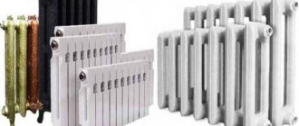
Coolant temperature
Increasing the cost of building residential real estate, construction companies are taking measures to insulate houses. But still, the temperature of the radiators is no less important. It depends on the temperature of the coolant, which fluctuates at different times and in different climatic conditions.
All requirements for coolant temperature are set out in building codes and regulations. When designing and commissioning engineering systems, these standards must be observed. For calculations, the temperature of the coolant at the outlet of the boiler is taken as a basis.
Indoor temperature standards vary. Eg:
- in the apartment the average is 20-22 degrees;
- in the bathroom it should be 25o;
- in the living room - 18o
In public non-residential premises, temperature standards are also different: in a school - 21o, in libraries and gyms - 18o, in a swimming pool - 30o, in industrial premises the temperature is set at about 16oC.
The more people gather indoors, the lower the temperature is initially set. In individual residential buildings, the owners themselves decide what temperature to set.
In order to set the desired temperature, it is important to consider the following factors:
- Availability of one-pipe or two-pipe system. For the first, the norm is 105°C, for 2 pipes - 95°C.
- In supply and discharge systems it should not exceed: 70-105°C for a single-pipe system and 70-95°C.
- Water flow in a certain direction: when distributing from above, the difference will be 20°C, from below - 30°C.
- Types of heating equipment used. They are divided by the method of heat transfer (radiation devices, convective and convective-radiation devices), by the material used in their manufacture (metal, non-metallic devices, combined), as well as by the magnitude of thermal inertia (small and large).
By combining various properties of the system, type of heating device, direction of water supply, etc., optimal results can be achieved.
How to regulate temperature
CHP workers are responsible for the parameters of heating mains, but monitoring of networks inside residential buildings is carried out by employees of the housing office or management companies. The Housing Office often receives complaints from residents that their apartments are cold. To normalize the system parameters, you will need to take the following measures:
- Increasing the nozzle diameter or installing an elevator with an adjustable nozzle. If there is an underestimated value of the liquid temperature in the return, then this problem can be solved by increasing the diameter of the elevator nozzle. To do this, you need to close the latches and valves, and then remove the module. The nozzle is enlarged by drilling it by 0.5-1 mm. After completing the procedure, the device is returned to its place, after which the procedure of bleeding air from the system must be carried out.
- Stop the choke. To avoid the threat of the suction pump performing the function of a jumper, it is silenced. To perform this procedure, a steel pancake is used, the thickness of which should be about 1 mm. This method of temperature control belongs to the category of emergency options, since when it is carried out, it is possible that a temperature jump of up to +130 degrees may occur.
- Regulation of differences. The problem can be resolved by adjusting the differences with an elevator valve. The essence of this correction method is to redirect the hot water to the supply pipe. A pressure gauge is screwed into the return pipe, after which the valve of the return pipeline is closed. When opening the valve, you need to check the pressure gauge readings.
If you install a conventional valve, this will lead to the system stopping and freezing. To reduce the difference, you need to increase the return pressure to 0.2 atm/day. You can find out what temperature the batteries should be based on the temperature graph. Knowing its value, you can check to ensure its compliance with the temperature regime.
In conclusion, it should be noted that options for suppressing suction and regulating differences are used exclusively in the development of critical situations. Knowing this minimum of information, you can contact the housing office or thermal power plant with complaints and wishes about the coolant in the system that does not meet the standards.
Adjustment methods
Dismantling the elevator unit
Which pipes are better for heating? Pipes for heating a private house - reviews, price
If the boiler room is responsible for the parameters of the coolant leaving the warm point, then the housing office workers must be responsible for the temperature inside the room. Many residents complain about the cold in their apartments. This occurs due to a deviation in the temperature graph. In rare cases, it happens that the temperature rises by a certain value.
Heating parameters can be adjusted in three ways:
- Reaming the nozzle.
If the supply and return coolant temperatures are significantly underestimated, then it is necessary to increase the diameter of the elevator nozzle. This way, more liquid will pass through it.
How to do this? To begin with, shut-off valves are closed (house valves and taps at the elevator unit). Next, the elevator and nozzle are removed. Then it is drilled out by 0.5-2 mm, depending on how much it is necessary to increase the temperature of the coolant. After these procedures, the elevator is mounted in its original place and put into operation.
To ensure sufficient tightness of the flange connection, it is necessary to replace the paronite gaskets with rubber ones.
- Silence the suction.
In severe cold weather, when the problem of freezing of the heating system in the apartment arises, the nozzle can be completely removed. In this case, the suction may become a jumper. To do this, you need to plug it with a steel pancake 1 mm thick. This process is carried out only in critical situations, since the temperature in pipelines and heating devices will reach 130ºC.
- Adjustment of difference.
In the middle of the heating season, a significant increase in temperature may occur. Therefore, it is necessary to regulate it using a special valve on the elevator. To do this, the supply of hot coolant is switched to the supply pipeline. A pressure gauge is mounted on the return line. Adjustment occurs by closing the valve on the supply pipeline. Next, the valve opens slightly, and the pressure should be monitored using a pressure gauge. If you simply open it, the cheeks will sag. That is, an increase in pressure drop occurs in the return pipeline. Every day the indicator increases by 0.2 atmospheres, and the temperature in the heating system must be constantly monitored.